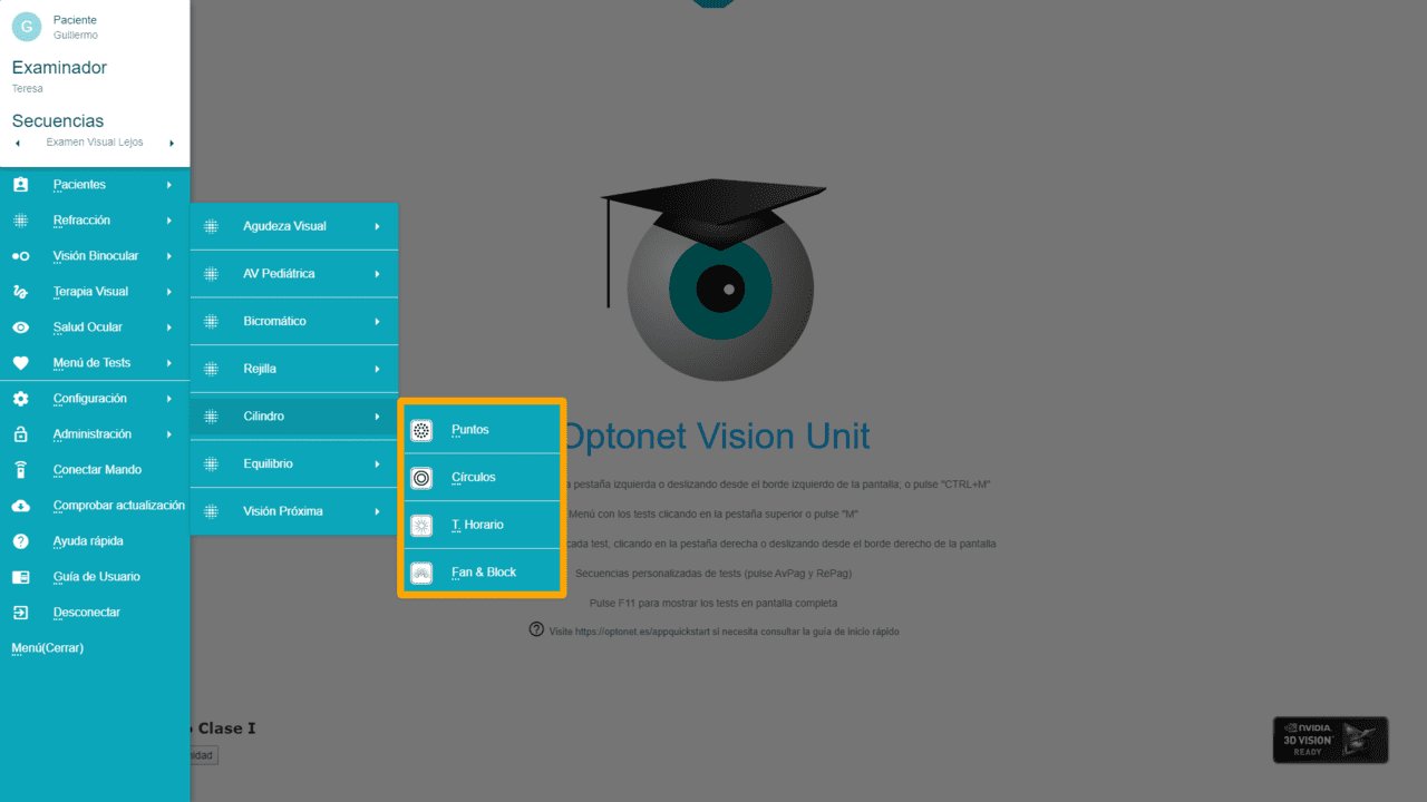
Within the “Refraction” group, there is a section of charts for determining the astigmatism refraction (the Cylinder). It contains four buttons that lead us to the Dots, Circles, Clock Dial, and Fan & Block charts, respectively.
Let’s enter each of these tests.
Dots and Circles charts #
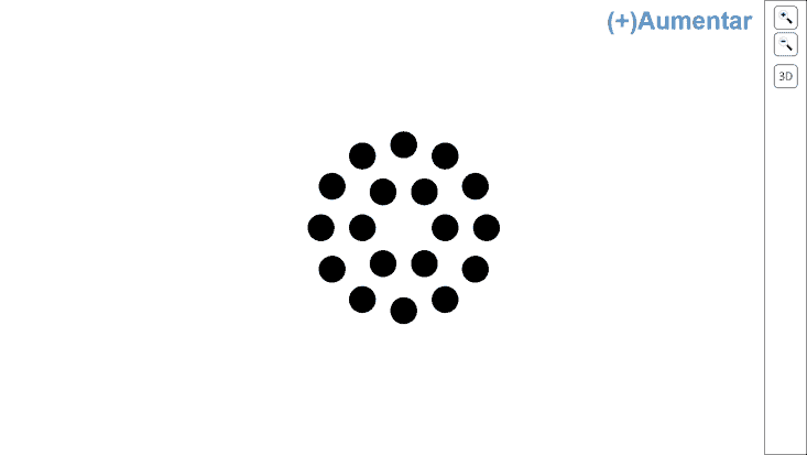
The Dots and concentric Circles charts are designed to verify the axis and power of astigmatism, with the help of the Jackson cross-cylinder (JCC). These charts have been designed to facilitate the detection of small changes in the image that occur with each turn of the JJC.*
Both charts offer zoom icons to increase and decrease their size.** The “+” and “-” keys can also be used, as usual. Each time the zoom icon is pressed, the size of the optotype is increased by a factor of 1.5X. The chosen size is automatically saved, so the next time the program is opened, these tests are displayed with the last selected size.
*An isolated row of Landolt Cs (one row above the current VA) can also be used as a target for the Jackson cross-cylinder.
**The initial size is 0.6 degrees for distance vision and 1.7 degrees for near vision.
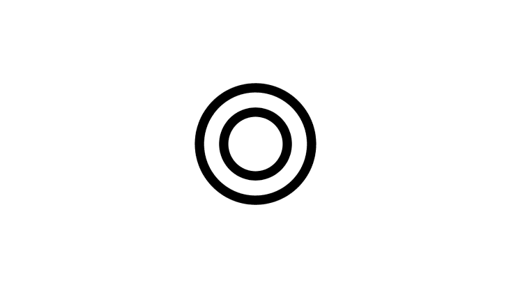
Clock Dial Chart #
The traditional Clock Dial Chart is also included to detect the presence of uncorrected astigmatism. The chart occupies the entire screen but can be resized using the usual icons and keys, with a zoom step of 1.125x. The tools menu also allows for the thickness of the lines to be increased or decreased using the corresponding icons (or the “Ctrl +” and “Ctrl -” key combinations, respectively).
The selected line size and thickness are automatically saved, so that the next time this chart is used, it will be displayed with the last selected size.
Although this chart can be used to determine the power and axis of the cylinder, it is normally reserved solely for detecting the presence of uncorrected astigmatism in people with reduced VA. For example, in patients with cataracts, who are unable to appreciate changes with the Jackson cross-cylinder.
Fan & Block Chart #
Within the Cylinder section, the Fan & Block chart is provided to accurately determine the axis and power of astigmatism.
This chart was designed to improve upon the traditional clock dial test’s accuracy. The clock dial test, with its 30-degree separation between lines, has limited sensitivity in determining the axis of astigmatism. Despite its widespread inclusion in chart systems, this is likely due to tradition rather than effectiveness.
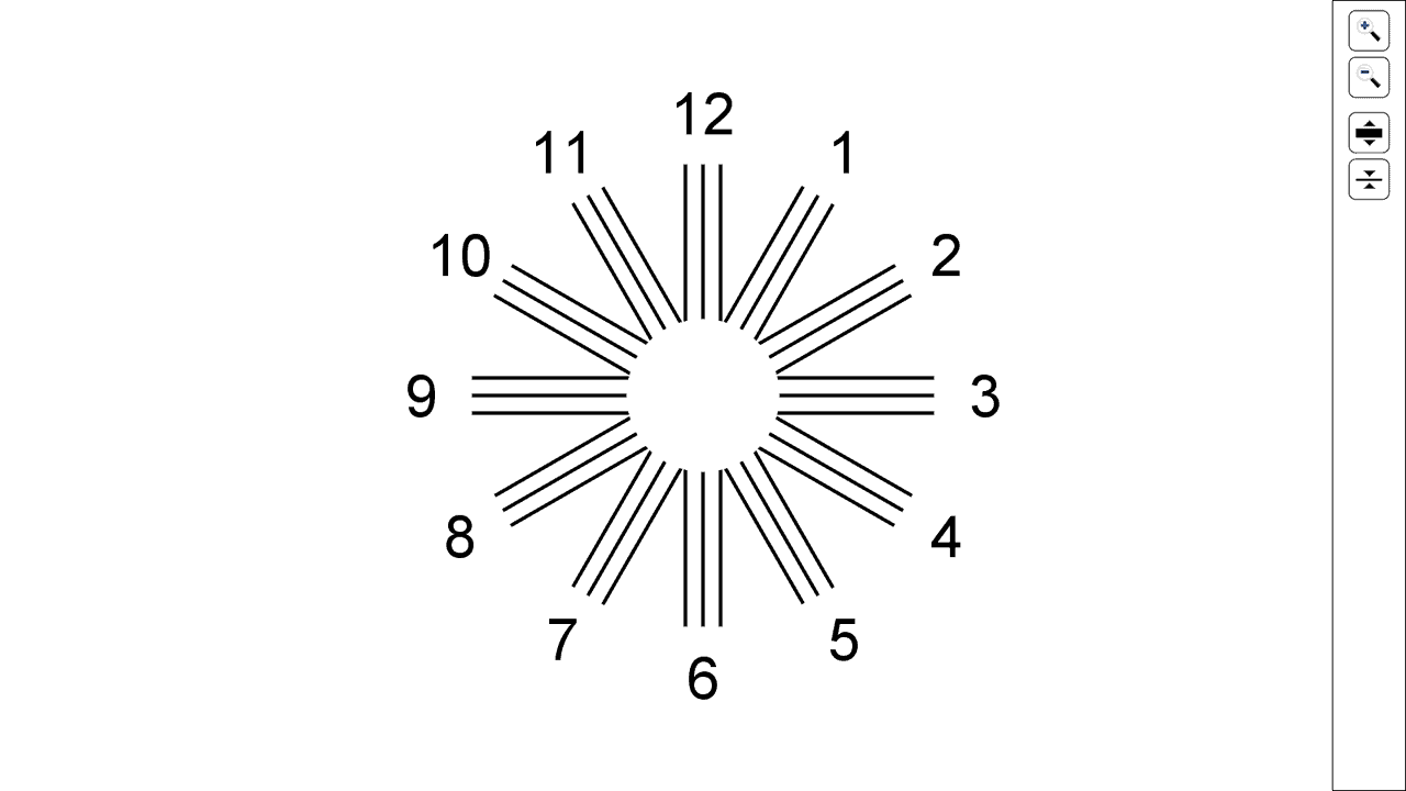
The Fan & Block chart features a radial pattern of lines across the screen, resembling the spokes of a wheel:
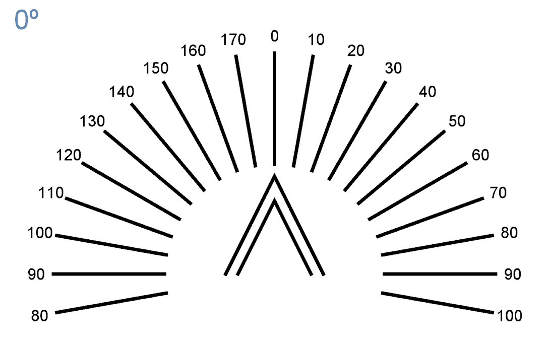
The lines are spaced at 10-degree intervals, as illustrated above. Additionally, numbers that indicate the degrees of orientation at which the corrective cylinder (negative) should be placed are displayed. These come into play when the patient identifies a specific line as the sharpest.
At the bottom centre of the display, an arrowhead feature is present, consisting of two sets of lines.
Controls #
The tool menu on the right side of the Fan & Block chart offers a series of controls described below:
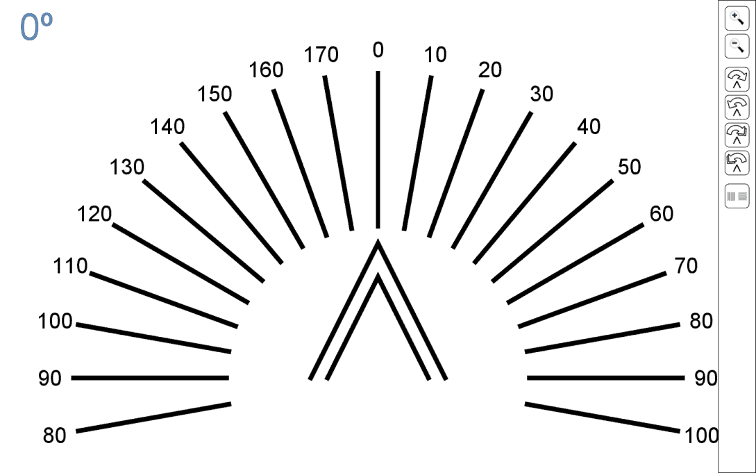
First, you can modify the thickness of the lines by clicking on the respective icons or by pressing the “+” and “-” keys on the keyboard. The selected thickness from the last session will be saved for future use. This functionality is beneficial for adjusting the line thickness to suit each clinic’s preferences.
The tool menu includes four buttons that enable rotation of the arrowhead in both clockwise and counterclockwise directions.
![]()
There are two rotation options: adjusting in 10-degree increments or fine-tuning by 1 degree at a time. This enables precise alignment of the arrow tip with the fan line that appears darkest to the patient.
Additionally, the left (←) and right (→) arrow keys on the keyboard can be used for 1-degree adjustments, while the up (↑) and down (↓) arrows facilitate 10-degree rotations.
When using 10-degree increments, the arrow precisely aligns with one of the lines on the fan.
For instance, in the image below, the arrow tip has been adjusted by 30 degrees to highlight the line identified by the patient as appearing darkest.
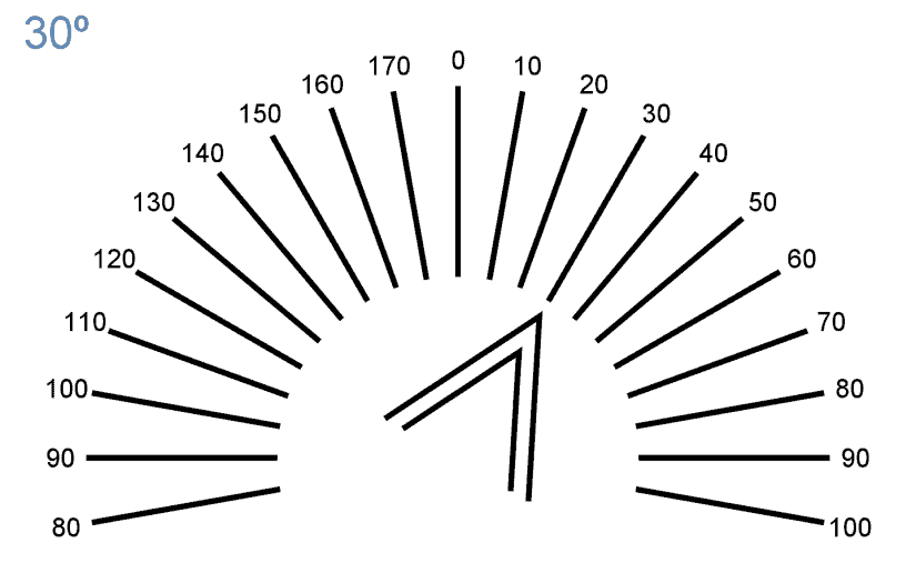
The rotation angle of the arrow tip is also displayed in the upper left corner of the screen. The number indicated represents the axis at which the negative cylinder should be positioned to correct the patient’s astigmatism, effectively marking the axis of the corrective cylinder.
On the right-hand side tool menu, an additional icon labelled (B)lock is available. This can be swiftly accessed by pressing the “B” key on the keyboard. Activating this icon reveals two blocks of lines covering the entire screen, positioned side by side. Importantly, the lines within one block are designed to be perpendicular to those in the adjacent block, ensuring a comprehensive assessment of astigmatism correction.
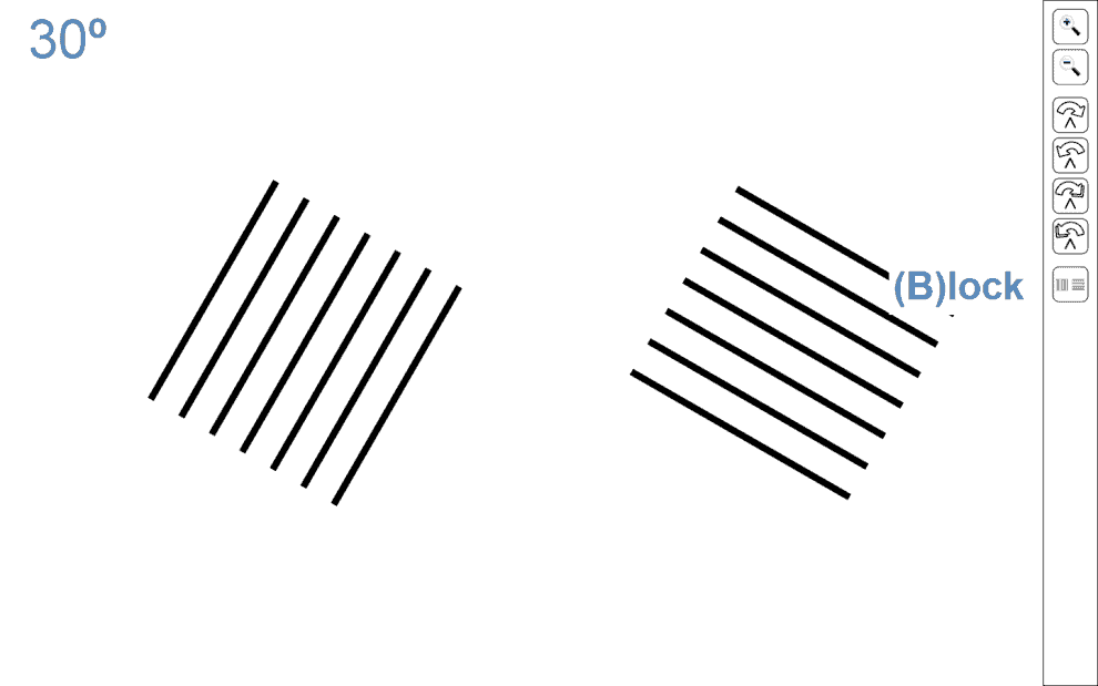
The left block will maintain the same orientation as indicated by the arrow tip on the previous screen, whereas the right block will feature lines that are perpendicular to those of the first. For instance, if the arrow tip was pointing to the line marked at 30 degrees, transitioning to the (B)lock test will present the initial configuration: the first block aligned with the 30-degree line from the fan, and the second block oriented perpendicularly. The line thickness within the blocks mirrors that of the fan lines and the arrow tip.
We will now outline the procedure of this test in 9 steps, aimed at acquainting those who may be new to it.
Procedure with the Fan & Block Test #
Cross-cylinders should not be the sole subjective method for determining astigmatism, as patient cooperation can vary with this approach. For such instances, the Fan & Block chart serves as an alternative.
The following steps start with objective refraction results obtained from retinoscopy or an autorefractometer as the reference point:
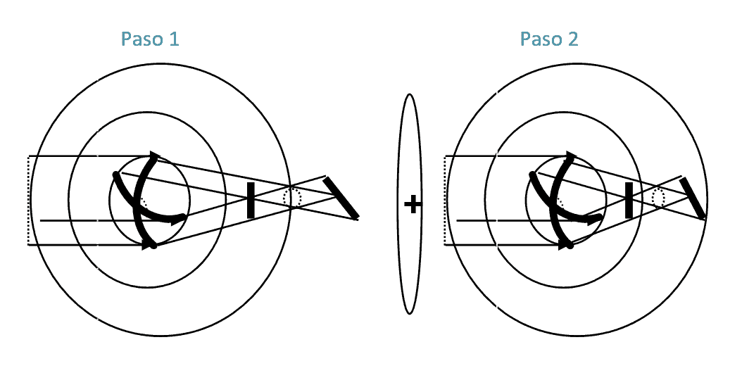
Step 1. Occlude the left eye (LE) and determine the maximum positive power that achieves the best visual acuity (MPMVA) or the “best sphere” for distance vision in the right eye (RE). (Keep the cylinder found during retinoscopy/autorefractometer in the phoropter/trial frame).
Step 2. Remove the minus cylinder determined through retinoscopy (or from autorefractometer readings) so that the patient is “fogged”. Add +0.50 DS to the spherical power to ensure that both focal lines and the circle of least confusion are in front of the retina.* Thus, each light point projects a blurry, oval-shaped image on the retina, oriented similarly to the light in the second focal point, making lines with this orientation appear sharper.
*Note: Uncorrected astigmatism causes each light point to focus at two distinct foci, forming lines perpendicular to each other. The “circle of least confusion” occurs roughly midway between these foci, where the light beam forms a circle.
**For near vision assessment with “Fan & Block,” add +3.00 DS to perform the test at 40 cm, positioning the circle of least confusion in front of the retina.
Step 3. Present the fan chart to the patient and inquire if any lines are perceived as darker/sharper/clearer.
Step 4. Should the patient report all lines as equally sharp or blurry, decrease the sphere by +0.50 DS and ask again. Uniform appearance across all lines indicates an absence of astigmatism.
Step 5. If a line appears darker, adjust the arrow tip in 10-degree increments to align with that specific line.
Step 6. Have the patient examine the lines at the arrow tip and determine if they are equally sharp or if one side is clearer. Adjust the arrow in 1-degree steps in both directions until the lines appear equally distinct. The screen’s upper left corner will display the axis, indicating the corrective cylinder’s required orientation.
Step 7. Click the block button on the right menu (or hit “B”) to transition to two blocks of perpendicular lines. The left block, aligned with the darker fan line, should look sharper than the right block of perpendicular lines.
Step 8. Position negative cylindrical lenses before the eye, aligned with the arrow’s indicated axis. Begin with a minimal prescription and incrementally adjust the power, asking the patient which block appears sharper. The goal is to equalize sharpness between both blocks. Should a reversal occur (the initially blurrier block becomes sharper), opt for the lesser cylindrical power.
Step 9. Adjust the spherical power to finalize the best sphere and repeat the procedure for the left eye (LE).
The most frequent error in this process is failing to position the astigmatism’s focal points in front of the retina throughout the test, meaning the patient isn’t adequately “fogged”.